现在我们到了 SeaBIOS 的 maininit 函数里,接下来还是一系列的初始化操作,初始化接口与设备,给接下来的 BootLoader 和操作系统提供基础环境。比如加载硬件、提供 BIOS 中断……
 1
 2
 3
 4
 5
 6
 7
 8
 9
10
11
12
13
14
15
16
17
18
19
|
static void maininit(void) {
    interface_init();
    platform_hardware_setup();
    if (threads_during_optionroms())
        device_hardware_setup();
    vgarom_setup();
    sercon_setup();
    enable_vga_console();
    if (!threads_during_optionroms()) {
        device_hardware_setup();
        wait_threads();
    }
    optionrom_setup();
    interactive_bootmenu();
    wait_threads();
    prepareboot();
    make_bios_readonly();
    startBoot();
}
|
可以发现在 maininit 最后一个函数调用 startBoot ,这个名字显而易见,开始启动。将会开始检查并运行引导扇区的内容。当该函数执行完成后,bios 的初始化工作就结束,接下来交给 BootLoader。但实际上 BIOS 还会为上层建筑提供运行时服务,这一块也是在 maininit 函数内初始化完毕的,之后就会留在 0xf0000 - 0xfffff BIOS 内存段内。接下来主要研究这些函数调用的实际用途,逐步构建起 BIOS 运行时环境然后交给 BootLoader。
interface_init
初始化内部接口:
 1
 2
 3
 4
 5
 6
 7
 8
 9
10
11
12
13
14
15
16
17
18
19
20
21
|
void interface_init(void) {
    // Running at new code address - do code relocation fixups
    malloc_init();

    // Setup romfile items.
    qemu_cfg_init();
    coreboot_cbfs_init();
    multiboot_init();

    // Setup ivt/bda/ebda
    ivt_init();
    bda_init();

    // Other interfaces
    boot_init();
    bios32_init();
    pmm_init();
    pnp_init();
    kbd_init();
    mouse_init();
}
|
先前已经有了 malloc_preinit 不过这是在 dopost 的代码重定位之前临时分配,而目前在代码重定位,整体都换到新的内存空间后又再一次正式的初始化内存分配器,为下文的操作提供动态内存分配。之前的内存分配位于 shadow ram 内,至于变量甚至都打上 Tmp 临时的标签,很显然这样的内存池只能支撑到重定位结束。之后伴随重定位,这些支撑临时内存池的指针之类的数据结构都无法使用,需要重新初始化。
malloc 如何从零开始内存分配
b820
要开始内存分配,需要知道内存的情况;如何知道内存情况,那么就需要知道内存有多少,可以提供一张表。现代计算机是这样的,BIOS 应该在开机自检的时候自己探测北桥得到的内存信息自己构建内存情况表。而 SeaBIOS 精简跳过了硬件探测,直接从 qemu 提供的接口里获得内存信息。qemu 通过 fw_cfg 硬件接口提供给 BIOS 各种设备信息。qemu 在 fw_cfg 提供了 e820 表,包含了内存信息。回到最开始 SeaBIOS 的 dopost() 函数,我们进入 qemu_preinit() 可以看到有如下与 e820 相关的代码:
 1
 2
 3
 4
 5
 6
 7
 8
 9
10
11
12
13
14
15
16
17
18
|
    // try read e820 table first
    if (!qemu_early_e820()) {
        // when it fails get memory size from nvram.
        u32 rs = ((rtc_read(CMOS_MEM_EXTMEM2_LOW) << 16)
                  | (rtc_read(CMOS_MEM_EXTMEM2_HIGH) << 24));
        if (rs)
            rs += 16 * 1024 * 1024;
        else
            rs = (((rtc_read(CMOS_MEM_EXTMEM_LOW) << 10)
                   | (rtc_read(CMOS_MEM_EXTMEM_HIGH) << 18))
                  + 1 * 1024 * 1024);
        RamSize = rs;
        e820_add(0, rs, E820_RAM);
        dprintf(1, "RamSize: 0x%08x [cmos]\n", RamSize);
    }

    /* reserve 256KB BIOS area at the end of 4 GB */
    e820_add(0xfffc0000, 256*1024, E820_RESERVED);
|
通过 qemu_early_e820() 读取 fw_cfg 里的 /etc/e820:
 1
 2
 3
 4
 5
 6
 7
 8
 9
10
11
|
// find e820 table
qemu_cfg_read_entry(&count, QEMU_CFG_FILE_DIR, sizeof(count));
count = be32_to_cpu(count);
for (i = 0; i < count; i++) {
    qemu_cfg_read(&qfile, sizeof(qfile));
    if (memcmp(qfile.name, "etc/e820", 9) != 0)
        continue;
    select = be16_to_cpu(qfile.select);
    size = be32_to_cpu(qfile.size);
    break;
}
|
具体不再往下深挖,e820 表好抽象,我们就假设 BIOS 已经帮我们做好了需要的内存表,在 seabios/src/e820map.h 内为我们提供了操作 e820 的接口:
 1
 2
 3
 4
 5
 6
 7
 8
 9
10
11
12
13
14
|
struct e820entry {
    u64 start;
    u64 size;
    u32 type;
};

void e820_add(u64 start, u64 size, u32 type);
void e820_remove(u64 start, u64 size);
void e820_prepboot(void);
int e820_is_used(u64 start, u64 size);

// e820 map storage
extern struct e820entry e820_list[];
extern int e820_count;
|
malloc_preinit
dopost 下的 malloc_preinit 分配了 ZoneTmpHigh、ZoneTmpLow 和 ZoneHigh 三大内存区。
主要是根据 e820 从高地址向下遍历寻找合适的内存地址。
为了方便,将一些宏直接展开了:
1
2
3
4
|
// e820_remove(u64 start, u64 size)
e820_remove(0xa0000, 0xf0000-0xa0000);
// e820_add(u64 start, u64 size, u32 type)
e820_add(0xf0000, 0x10000, E820_RESERVED);
|
第一行从 e820 移除了 0xa0000 ~ 0x100000 区间的内存,这块内存是硬件占用区,不能用做内存分配,而第二行将 0xf0000 ~ 0x10000 这段空间标注为保留,这一段是 BIOS 在ISA 内存段的映射。
 1
 2
 3
 4
 5
 6
 7
 8
 9
10
11
12
13
14
15
16
17
18
19
20
21
22
23
24
25
26
27
28
29
30
|
u32 highram_start = 0;
u32 highram_size = 0;
int i;
for (i=e820_count-1; i>=0; i--) {
    struct e820entry *en = &e820_list[i];
    u64 end = en->start + en->size;
    if (end < 1024*1024)
        break;
    if (en->type != E820_RAM || end > 0xffffffff)
        continue;
    u32 s = en->start, e = end;
    if (!highram_start) {
        u32 new_max = ALIGN_DOWN(e - BUILD_MAX_HIGHTABLE, MALLOC_MIN_ALIGN);
        u32 new_min = ALIGN_DOWN(e - BUILD_MIN_HIGHTABLE, MALLOC_MIN_ALIGN);
        if (new_max <= e && new_max >= s + BUILD_MAX_HIGHTABLE) {
            highram_start = e = new_max;
            highram_size = BUILD_MAX_HIGHTABLE;
        } else if (new_min <= e && new_min >= s) {
            highram_start = e = new_min;
            highram_size = BUILD_MIN_HIGHTABLE;
        }
    }
    alloc_add(&ZoneTmpHigh, s, e);
}

alloc_add(&ZoneTmpLow, BUILD_STACK_ADDR, BUILD_EBDA_MINIMUM);
if (highram_start) {
    alloc_add(&ZoneHigh, highram_start, highram_start + highram_size);
    e820_add(highram_start, highram_size, E820_RESERVED);
}
|
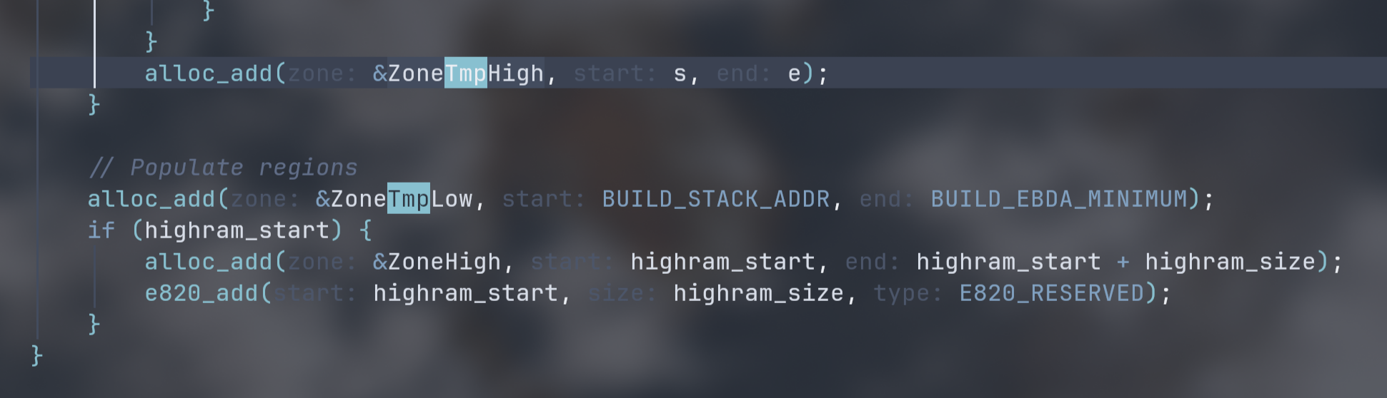
首先从 e820 表的高地址段向低地址段读,而且是在 4GB ~ 1MB 之间寻找查找 16 MB 大小的可用块加入 ZoneTmpHigh,如果没有 16MB 大小就退而求其次选择 256 KB 给 ZoneTmpHigh。这块区域用做重定位前的临时动态内存分配空间。这一块通常很大,将高区所有可用的内存都分配给 ZoneTmpHigh 了。
接下来在低区分配一段连续的内存空间存放数据。因为各种历史包袱,还是很需要 1MB 以内的空间给 BIOS 在实模式下使用,这种就放在 ZoneTmpLow 下。
1
|
alloc_add(&ZoneTmpLow, 0x7000, 0x90000);
|
如果我们往前看代码会发现 new_max/new_min 实际会分配到在变量 e 去掉的一小块内存:
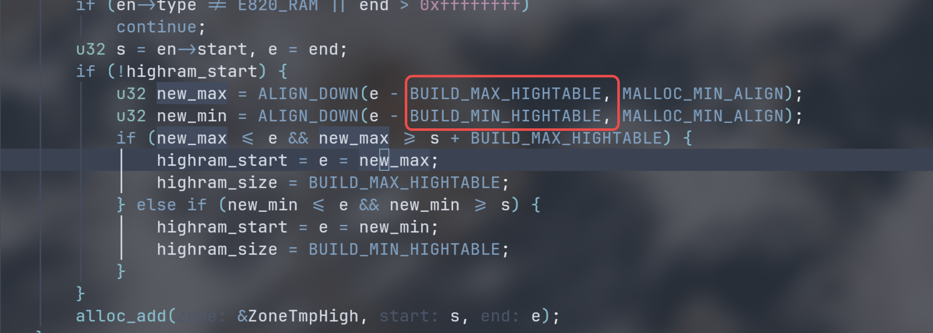
这一个宏就被保存到 highram_size 内。BUILD_MAX_HIGHTABLE 为 16MB,BUILD_MIN_HIGHTABLE 为 256 KB。
这样就会在 highram_start ~ highram_start + highram_size 这一小块内存给 ZoneHigh,作为永久高区保留下来。
并且还会通过 e820_add 将其类型做保留,这样就不会在之后被操作系统利用。
1
2
3
4
|
if (highram_start) {
    alloc_add(&ZoneHigh, highram_start, highram_start + highram_size);  // 高区永久
    e820_add(highram_start, highram_size, E820_RESERVED);    // 保留
}
|
以上就是 dopost 阶段的 malloc_preinit 主要逻辑。算是一个小插曲把。接下来回到 maininit 的 interface_init 中的 malloc_init 在重定位后 SeaBIOS 又再一次进行 malloc 初始化:
malloc_init
这里是进入 maininit 后实际做的第一件事,初始化好 malloc。
1
2
3
4
5
6
7
8
9
|
if (CONFIG_RELOCATE_INIT) {
    // Fixup malloc pointers after relocation
    int i;
    for (i=0; i<ARRAY_SIZE(Zones); i++) {
        struct zone_s *zone = Zones[i];
        if (zone->head.first)
            zone->head.first->pprev = &zone->head.first;
    }
}
|
首先修复重定位后空闲链表指针错误的问题。这又要扯到 SeaBIOS 分配器中的数据结构……
struct zone_s 仅存储指向第一个节点的指针。
 1
 2
 3
 4
 5
 6
 7
 8
 9
10
11
12
|
// The various memory zones.
struct zone_s {
    struct hlist_head head;
};

struct hlist_head {
    struct hlist_node *first;
};

struct hlist_node {
    struct hlist_node *next, **pprev;
};
|
往前追溯才能看到其底层就两指针:next 和 pprev,pprev 。具体的 hlist 的实现可以看:https://github.com/coreboot/seabios/blob/master/src/list.h#L11。
这里将旧的 zone->head.first->pprev 修复为新的 zone->head.first。完成重定向后空闲块链表的修复。这个空闲块链表等以后再细讲吧,这种侵入式双向链表研究起来挺有意义的。
初始化低区
 1
 2
 3
 4
 5
 6
 7
 8
 9
10
|
    memmove(VSYMBOL(final_varlow_start), VSYMBOL(varlow_start)
            , SYMBOL(varlow_end) - SYMBOL(varlow_start));
    if (CONFIG_MALLOC_UPPERMEMORY) {
        alloc_add(&ZoneLow, SYMBOL(zonelow_base) + OPROM_HEADER_RESERVE
                  , SYMBOL(final_varlow_start));
        RomBase = alloc_find_lowest(&ZoneLow);
    } else {
        alloc_add(&ZoneLow, ALIGN_DOWN(SYMBOL(final_varlow_start), 1024)
                  , SYMBOL(final_varlow_start));
    }
|
将 F 段(0xf0000 - 0xfffff) 可供动态内存分配的区域(zonefseg_start ~ zonefseg_end) 写零,并注册到 F 段内存分配器。
1
2
3
4
|
    // Add space available in f-segment to ZoneFSeg
    memset(VSYMBOL(zonefseg_start), 0
           , SYMBOL(zonefseg_end) - SYMBOL(zonefseg_start));
    alloc_add(&ZoneFSeg, SYMBOL(zonefseg_start), SYMBOL(zonefseg_end));
|
计算最大可用的内存区域。
初始化 romfile 条目
SeaBIOS 使用内部的 romfile 系统来管理启动时的固件配置、ACPI 表和选项 ROM,在 interface_init() 中有如下三条函数,分别对应不同的机器:
1
2
3
4
|
    // Setup romfile items.
    qemu_cfg_init();
    coreboot_cbfs_init();
    multiboot_init();
|
因为我们从 qemu 而来,所以就只看 qemu_cfg_init():
忽略对 qemu 的判断,来到 qemu_cfg_legacy:
1
2
|
// Populate romfiles for legacy fw_cfg entries
qemu_cfg_legacy();
|
这里将会读取传统 fw_cfg 接口下的数据:主要有 NUMA 数据、ACPI 表、SMBIOS 信息。
传统的 fw_cfg 写死了 selector 键值,在 seabios/src/fw/paravirt.c#L333 行的各种宏确定了键值。
比如读取 ACPI 表:
 1
 2
 3
 4
 5
 6
 7
 8
 9
10
11
12
13
14
|
// ACPI tables
char name[128];
u16 cnt;
qemu_cfg_read_entry(&cnt, QEMU_CFG_ACPI_TABLES, sizeof(cnt));
int i, offset = sizeof(cnt);
for (i = 0; i < cnt; i++) {
    u16 len;
    qemu_cfg_read(&len, sizeof(len));
    offset += sizeof(len);
    snprintf(name, sizeof(name), "acpi/table%d", i);
    qemu_romfile_add(name, QEMU_CFG_ACPI_TABLES, offset, len);
    qemu_cfg_skip(len);
    offset += len;
}
|
通过前面预先设定好的宏确定 fw_cfg 条目的选择器键。fw_cfg 是 qemu 提供的端口用于将配置文件从 QEMU 传递给客户固件,SeaBIOS 的端口宏:
1
2
3
4
|
#define PORT_QEMU_CFG_CTL           0x0510
#define PORT_QEMU_CFG_DATA          0x0511
#define PORT_QEMU_CFG_DMA_ADDR_HIGH 0x0514
#define PORT_QEMU_CFG_DMA_ADDR_LOW  0x0518
|
读取 romfile 的函数:
 1
 2
 3
 4
 5
 6
 7
 8
 9
10
11
12
13
14
15
16
|
static void
qemu_romfile_add(char *name, int select, int skip, int size)
{
    struct qemu_romfile_s *qfile = malloc_tmp(sizeof(*qfile));
    if (!qfile) {
        warn_noalloc();
        return;
    }
    memset(qfile, 0, sizeof(*qfile));
    strtcpy(qfile->file.name, name, sizeof(qfile->file.name));
    qfile->file.size = size;
    qfile->select = select;
    qfile->skip = skip;
    qfile->file.copy = qemu_cfg_read_file;
    romfile_add(&qfile->file);
}
|
每一个 romfile 用 struct romfile_s 抽象出来:
 1
 2
 3
 4
 5
 6
 7
 8
 9
10
11
|
struct qemu_romfile_s {
    struct romfile_s file;
    int select, skip;
};

struct romfile_s {
    struct romfile_s *next; // 链表指针
    char name[128]; // 文件名
    u32 size; // 文件大小
    int (*copy)(struct romfile_s *file, void *dest, u32 maxlen); // 读取方法(函数指针)
};
|
这样抽象化之后所有机器的固件都可以用 romfile_find() 函数进行读取。
在这之后开始读取现代 fw_cfg 的条目。现代 fw_cfg 引入了 File Directory 的基址,在固定键值上维护文件索引表,这样就能通过遍历更灵活地调整。
 1
 2
 3
 4
 5
 6
 7
 8
 9
10
11
|
    // Load files found in the fw_cfg file directory
    u32 count;
    qemu_cfg_read_entry(&count, QEMU_CFG_FILE_DIR, sizeof(count));
    count = be32_to_cpu(count);
    u32 e;
    for (e = 0; e < count; e++) {
        struct QemuCfgFile qfile;
        qemu_cfg_read(&qfile, sizeof(qfile));
        qemu_romfile_add(qfile.name, be16_to_cpu(qfile.select)
                         , 0, be32_to_cpu(qfile.size));
    }
|
如上,seabios 通过 qemu_cfg_read_entry 读取 fw_cfg 条数,通过循环遍历读完 fw_cfg 数据。
fw_cfg 数据端口上一个流式读取器,不需要重新 select 就直接在同一个数据流中往下读。
和 ACPI 表加载项有关的部分:
1
2
3
4
|
if (romfile_find("etc/table-loader")) {
    acpi_pm_base = 0x0600;
    dprintf(1, "Moving pm_base to 0x%x\n", acpi_pm_base);
}
|
qemu 是否在串口模式。
1
2
3
4
5
6
|
// serial console
u16 nogfx = 0;
qemu_cfg_read_entry(&nogfx, QEMU_CFG_NOGRAPHIC, sizeof(nogfx));
if (nogfx && !romfile_find("etc/sercon-port")
    && !romfile_find("vgaroms/sgabios.bin"))
    const_romfile_add_int("etc/sercon-port", PORT_SERIAL1);
|
初始化中断向量表
BIOS 通过中断提供给操作系统之类的应用程序调用计算机硬件的功能,这些功能由 BIOS 抽象封装,程序通过 int 指令可以直接调用。当发生中断时,BIOS 通过在内存中的中断向量表(IVT) 找到需要调用的中断服务例程(ISR)。
中断向量表有 256 个项,位于物理内存的 0x0000:0000 每个向量占 4 字节(从 0x0000-0x0400 占 1kb)。在 SeaBIOS 中,初始化完成 malloc 和 fw_cfg 表后就通过 ivt_init 初始化中断向量表。
 1
 2
 3
 4
 5
 6
 7
 8
 9
10
11
12
13
14
15
16
17
18
19
20
21
22
23
24
25
26
27
28
29
30
31
32
33
34
35
36
37
38
39
40
|
static void
ivt_init(void)
{
    dprintf(3, "init ivt\n");

    // Initialize all vectors to the default handler.
    int i;
    for (i=0; i<256; i++)
        SET_IVT(i, FUNC16(entry_iret_official));

    // Initialize all hw vectors to a default hw handler.
    for (i=BIOS_HWIRQ0_VECTOR; i<BIOS_HWIRQ0_VECTOR+8; i++)
        SET_IVT(i, FUNC16(entry_hwpic1));
    for (i=BIOS_HWIRQ8_VECTOR; i<BIOS_HWIRQ8_VECTOR+8; i++)
        SET_IVT(i, FUNC16(entry_hwpic2));

    // Initialize software handlers.
    SET_IVT(0x02, FUNC16(entry_02));
    SET_IVT(0x05, FUNC16(entry_05));
    SET_IVT(0x10, FUNC16(entry_10)); // 视频服务
    SET_IVT(0x11, FUNC16(entry_11));
    SET_IVT(0x12, FUNC16(entry_12));
    SET_IVT(0x13, FUNC16(entry_13_official)); // 磁盘服务
    SET_IVT(0x14, FUNC16(entry_14));
    SET_IVT(0x15, FUNC16(entry_15_official)); // 系统服务
    SET_IVT(0x16, FUNC16(entry_16));
    SET_IVT(0x17, FUNC16(entry_17));
    SET_IVT(0x18, FUNC16(entry_18));
    SET_IVT(0x19, FUNC16(entry_19_official));
    SET_IVT(0x1a, FUNC16(entry_1a_official));
    SET_IVT(0x40, FUNC16(entry_40));

    // INT 60h-66h reserved for user interrupt
    for (i=0x60; i<=0x66; i++)
        SET_IVT(i, SEGOFF(0, 0));

    // set vector 0x79 to zero
    // this is used by 'gardian angel' protection system
    SET_IVT(0x79, SEGOFF(0, 0));
}
|
SeaBIOS 将所有 256 个中断向量初始化为默认处理程序:entry_iret_official,该函数就执行一个 iretw 指令返回:
1
2
3
4
|
        ORG 0xff53
        .global entry_iret_official
entry_iret_official:
        iretw
|
用 entry_hwpic1 和 entry_hwpic2 初始化 pic 硬件中断:
1
2
3
4
5
|
// Initialize all hw vectors to a default hw handler.
for (i=BIOS_HWIRQ0_VECTOR; i<BIOS_HWIRQ0_VECTOR+8; i++)
    SET_IVT(i, FUNC16(entry_hwpic1)); // 主 PIC 硬件中断处理程序 (0x08-0x0f)
for (i=BIOS_HWIRQ8_VECTOR; i<BIOS_HWIRQ8_VECTOR+8; i++)
    SET_IVT(i, FUNC16(entry_hwpic2)); // 从 PIC 硬件中断处理程序 (0x70-0x77)
|
这里我还不太懂,先就这样。
接下来初始化软件中断处理程序也就是 BIOS 服务:
 1
 2
 3
 4
 5
 6
 7
 8
 9
10
11
12
13
14
15
|
// Initialize software handlers.
SET_IVT(0x02, FUNC16(entry_02)); // NMI 不可屏蔽中断
SET_IVT(0x05, FUNC16(entry_05)); // 打印屏幕服务
SET_IVT(0x10, FUNC16(entry_10)); // 视频服务
SET_IVT(0x11, FUNC16(entry_11)); // 获取设备列表
SET_IVT(0x12, FUNC16(entry_12)); // 获取内存大小
SET_IVT(0x13, FUNC16(entry_13_official)); // 磁盘服务
SET_IVT(0x14, FUNC16(entry_14)); // 串口服务
SET_IVT(0x15, FUNC16(entry_15_official)); // 系统服务
SET_IVT(0x16, FUNC16(entry_16)); // 键盘服务
SET_IVT(0x17, FUNC16(entry_17)); // 打印机服务
SET_IVT(0x18, FUNC16(entry_18)); // 启动 ROM BASIC
SET_IVT(0x19, FUNC16(entry_19_official)); // 引导加载服务
SET_IVT(0x1a, FUNC16(entry_1a_official)); // 实时时钟服务
SET_IVT(0x40, FUNC16(entry_40)); // 软盘服务
|
将用户保留的中断置 0(覆盖为 0000:0000)
1
2
3
4
5
6
7
|
// INT 60h-66h reserved for user interrupt
for (i=0x60; i<=0x66; i++)
    SET_IVT(i, SEGOFF(0, 0));

// set vector 0x79 to zero
// this is used by 'gardian angel' protection system
SET_IVT(0x79, SEGOFF(0, 0));
|
以上就是完整的 SeaBIOS 对中断向量表的初始化过程,实际上中断向量表就是在内存最开始的那一段函数指针数组。
初始化 BIOS Data Area
1
2
|
struct bios_data_area_s *bda = MAKE_FLATPTR(SEG_BDA, 0);
memset(bda, 0, sizeof(*bda));
|
C 函数中,编译器生成的代码是 32 位 flat 保护模式下运行的,所以这里要将该地址转换为 flat 模式,实际就是一个位运算宏:
1
|
#define MAKE_FLATPTR(seg,off) ((void*)(((u32)(seg)<<4)+(u32)(off)))
|
stuct bios_data_area_s 是非常规整的结构体,保存了很多成员变量,在 /seabios/src/std/bda.h#L22 里。memset 将所有成员都置零。
1
2
3
4
5
6
7
8
9
|
//  确定 EBDA 的位置和大小
int esize = EBDA_SIZE_START;
u16 ebda_seg = EBDA_SEGMENT_START;
if (!CONFIG_MALLOC_UPPERMEMORY)
    ebda_seg = FLATPTR_TO_SEG(ALIGN_DOWN(SYMBOL(final_varlow_start), 1024)
                              - EBDA_SIZE_START*1024);
// 在 BDA 中记录内存大小和 EBDA 段
SET_BDA(ebda_seg, ebda_seg);
SET_BDA(mem_size_kb, ebda_seg / (1024/16));
|
初始化 EBDA
1
2
3
4
5
|
struct extended_bios_data_area_s *ebda = get_ebda_ptr();
memset(ebda, 0, sizeof(*ebda));
ebda->size = esize;

e820_add((u32)ebda, BUILD_LOWRAM_END-(u32)ebda, E820_RESERVED); // 保留该内存
|
设置额外堆栈:
1
|
StackPos = &ExtraStack[BUILD_EXTRA_STACK_SIZE] - SYMBOL(zonelow_base);
|
初始化引导顺序和启动参数
boot_init() 在 QEMU 下有更多的配置。首先引入 u8 rtc_read(u8 index) 函数:
1
2
3
4
5
6
7
8
|
// seabios/src/hw/rtc.c
u8
rtc_read(u8 index)
{
    index |= NMI_DISABLE_BIT;
    outb(index, PORT_CMOS_INDEX);
    return inb(PORT_CMOS_DATA);
}
|
RTC 是实时时钟芯片用于保持计算机时钟精准。其内部包含由电池供电的 CMOS RAM,用来保存 BIOS 设置。
在这里,会向 PORT_CMOS_INDEX(0x70) 端口写入 index 选择要读的寄存器索引,然后向 PORT_CMOS_DATA(0x71) 数据端口读出值。
最开始通过 CMOS_BIOS_BOOTFLAG1 的 bit 0 判断是否开启软盘签名检查,之后拼接 CMOS_BIOS_BOOTFLAG1 & 0xf0 (其的高 4 位) 和 CMOS_BIOS_BOOTFLAG2 组合成 12 位的引导顺序编码。
1
2
3
4
5
6
|
if (rtc_read(CMOS_BIOS_BOOTFLAG1) & 1)
    CheckFloppySig = 0;
u32 bootorder = (rtc_read(CMOS_BIOS_BOOTFLAG2)
                 | ((rtc_read(CMOS_BIOS_BOOTFLAG1) & 0xf0) << 4));
DefaultFloppyPrio = DefaultCDPrio = DefaultHDPrio
    = DefaultBEVPrio = DEFAULT_PRIO; // 将 4 类设备的默认优先级重置为最低
|
DEFAULT_PRIO 为 9999。变量数字越小的引导优先级越高。
 1
 2
 3
 4
 5
 6
 7
 8
 9
10
|
int i;
for (i=101; i<104; i++) {
    u32 val = bootorder & 0x0f;
    bootorder >>= 4;
    switch (val) {
    case 1: DefaultFloppyPrio = i; break;
    case 2: DefaultHDPrio = i;     break;
    case 3: DefaultCDPrio = i;     break;
    case 4: DefaultBEVPrio = i;    break;
    }
|
这里每一次取出 bootorder 的低 4 位:cal = bootorder & 0x0f 然后将 bootorder 右移 4 位:bootorder >>=4 根据 var 的值设置对应设备的优先级为 i。所以最先取出的设备优先级为 101 最高。这样就可以说明,bootorder 12 位每 4 位为一个设备,低位优先级更高,因为更先取出来。
1
2
3
4
5
|
// 从 fw_cfg 设备读取 etc/boot-fail-wait 确定引导失败重试等待时间
BootRetryTime = romfile_loadint("etc/boot-fail-wait", 60*1000);

loadBootOrder(); // 从 fw_cfg 的 bootorder 中读取更明确的引导设备列表。
loadBiosGeometry(); // 从 fw_cfg 中加载磁盘几何参数
|
加载 BIOS32 服务目录
 1
 2
 3
 4
 5
 6
 7
 8
 9
10
11
12
13
14
15
16
17
18
19
20
21
22
23
|
// seabios/src/pcibios.c
struct bios32_s {
    u32 signature;
    u32 entry;
    u8 version;
    u8 length;
    u8 checksum;
    u8 reserved[5];
} PACKED;

struct bios32_s BIOS32HEADER __aligned(16) VARFSEG = {
    .signature = 0x5f32335f, // _32_
    .length = sizeof(BIOS32HEADER) / 16,
};

void
bios32_init(void)
{
    dprintf(3, "init bios32\n");

    BIOS32HEADER.entry = (u32)entry_bios32;
    BIOS32HEADER.checksum -= checksum(&BIOS32HEADER, sizeof(BIOS32HEADER));
}
|
BIOS32 是可以在保护模式下调用 BIOS 服务的方法,通常用于 PIC 和即插即用的服务。上面为初始化 BIOS32 的方法。
加载 PMM(Post Memory Manager)
PMM 是启动期的内存管理服务,用于对外给各个组件一个标准化的内容服务接口。
 1
 2
 3
 4
 5
 6
 7
 8
 9
10
11
|
void
pmm_init(void)
{
    if (! CONFIG_PMM)
        return;

    dprintf(3, "init PMM\n");

    PMMHEADER.entry = FUNC16(entry_pmm);
    PMMHEADER.checksum -= checksum(&PMMHEADER, sizeof(PMMHEADER));
}
|
这里通过 entry_pmm 跳转到 C 函数:handle_pmm:
 1
 2
 3
 4
 5
 6
 7
 8
 9
10
11
12
13
14
15
16
17
18
19
20
21
|
// seabios/src/pmm.c
u32 VISIBLE32INIT
handle_pmm(u16 *args)
{
    ASSERT32FLAT();
    if (! CONFIG_PMM)
        return PMM_FUNCTION_NOT_SUPPORTED;

    u16 arg1 = args[0];
    dprintf(DEBUG_HDL_pmm, "pmm call arg1=%x\n", arg1);

    u32 ret;
    switch (arg1) {
    case 0x00: ret = handle_pmm00(args); break; // allocate
    case 0x01: ret = handle_pmm01(args); break; // find
    case 0x02: ret = handle_pmm02(args); break; // deallocate
    default:   ret = handle_pmmXX(args); break; // not supportedd
    }

    return ret;
}
|
初始化 PNP BIOS call
 1
 2
 3
 4
 5
 6
 7
 8
 9
10
11
12
|
void
pnp_init(void)
{
    if (! CONFIG_PNPBIOS)
        return;

    dprintf(3, "init PNPBIOS table\n");

    PNPHEADER.real_ip = (u32)entry_pnp_real - BUILD_BIOS_ADDR;
    PNPHEADER.prot_ip = (u32)entry_pnp_prot - BUILD_BIOS_ADDR;
    PNPHEADER.checksum -= checksum(&PNPHEADER, sizeof(PNPHEADER));
}
|
php 和 BIOS 32 类似。php 即 plug and play,即插即用。
初始化键盘请求
 1
 2
 3
 4
 5
 6
 7
 8
 9
10
11
12
13
14
|
// seabios/src/kbd.c
void
kbd_init(void)
{
    dprintf(3, "init keyboard\n");
    u16 x = offsetof(struct bios_data_area_s, kbd_buf);
    SET_BDA(kbd_flag1, KF1_101KBD);
    SET_BDA(kbd_buf_head, x);
    SET_BDA(kbd_buf_tail, x);
    SET_BDA(kbd_buf_start_offset, x);

    SET_BDA(kbd_buf_end_offset
            , x + FIELD_SIZEOF(struct bios_data_area_s, kbd_buf));
}
|
核心在于初始化 BIOS 数据区中与键盘相关的字段,建立键盘缓冲区环,为硬件中断 int 9h 和 int 16h 做好准备。
初始化鼠标
 1
 2
 3
 4
 5
 6
 7
 8
 9
10
|
// seabios/src/mouse.c
void
mouse_init(void)
{
    if (! CONFIG_MOUSE)
        return;
    dprintf(3, "init mouse\n");
    // pointing device installed
    set_equipment_flags(0x04, 0x04);
}
|
这里仅将 BDA 中的设备标志字中的 bit 2 置 1 指示鼠标已安装。
到这里,内部接口就初始化完毕了。
设置平台硬件。
 1
 2
 3
 4
 5
 6
 7
 8
 9
10
11
12
13
14
15
16
17
18
19
20
21
22
|
static void
platform_hardware_setup(void)
{
    // Make sure legacy DMA isn't running.
    dma_setup();

    // Init base pc hardware.
    pic_setup();
    thread_setup();
    mathcp_setup();

    // Platform specific setup
    qemu_platform_setup();
    coreboot_platform_setup();

    // Setup timers and periodic clock interrupt
    timer_setup();
    clock_setup();

    // Initialize TPM
    tpm_setup();
}
|
dma 控制器初始化
 1
 2
 3
 4
 5
 6
 7
 8
 9
10
11
|
void
dma_setup(void)
{
    // first reset the DMA controllers
    outb(0, PORT_DMA1_MASTER_CLEAR);
    outb(0, PORT_DMA2_MASTER_CLEAR);

    // then initialize the DMA controllers
    outb(0xc0, PORT_DMA2_MODE_REG);
    outb(0x00, PORT_DMA2_MASK_REG);
}
|
PORT_DMA1_MASTER_CLEAR 是 0xd 发复位命令。向其写 0 对 dma 进行复位,PORT_DMA2_MASTER_CLEAR 同理。
这样命令、状态、请求、暂存寄存器被清零,内部字节指针触发器被复位,所有通道的屏蔽位被置位,之后控制器进入空闲状态,使得两个 DMA 芯片恢复到已知的干净状态。
而向 PORT_DMA2_MASK_REG(0xd6) 写 0xc0:outb(0xc0, PORT_DMA2_MODE_REG); 0xd6 是写方式寄存器,写入 0b11000000 配置 DMA2 的通道 0 固定用于级联 DMA1(deepseek 给的说法,8237 真不懂😕)
outb(0x00, PORT_DMA2_MASK_REG); 向单通道屏蔽寄存器(0xd4) 写 0 清除屏蔽位。
DMA 暂且这样,有点复杂啊……
初始化 PIC(8259A 可编程中断控制器)
 1
 2
 3
 4
 5
 6
 7
 8
 9
10
11
12
13
14
15
16
17
18
19
20
21
22
23
24
25
26
27
|
void
pic_reset(u8 irq0, u8 irq8)
{
    if (!CONFIG_HARDWARE_IRQ)
        return;
    // Send ICW1 (select OCW1 + will send ICW4)
    outb(0x11, PORT_PIC1_CMD);
    outb(0x11, PORT_PIC2_CMD);
    // Send ICW2 (base irqs: 0x08-0x0f for irq0-7, 0x70-0x77 for irq8-15)
    outb(irq0, PORT_PIC1_DATA);
    outb(irq8, PORT_PIC2_DATA);
    // Send ICW3 (cascaded pic ids)
    outb(0x04, PORT_PIC1_DATA);
    outb(0x02, PORT_PIC2_DATA);
    // Send ICW4 (enable 8086 mode)
    outb(0x01, PORT_PIC1_DATA);
    outb(0x01, PORT_PIC2_DATA);
    // Mask all irqs (except cascaded PIC2 irq)
    pic_irqmask_write(PIC_IRQMASK_DEFAULT);
}

void
pic_setup(void)
{
    dprintf(3, "init pic\n");
    pic_reset(BIOS_HWIRQ0_VECTOR, BIOS_HWIRQ8_VECTOR);
}
|
与 CPU 相连有主从两片级联的 8259A 负责串联起 CPU 与可屏蔽中断,这些中断由外部硬件发送给 8259A。系统提供了两个端口地址:主片 0x20 和 0x21,从片 0xa0 和 0xa1。
上面的 pic_reset() 仅初始化了 PIC 配置:
写 ICW1,向主从命令口写入 0x11,开始初始化并后续会发送 ICW4:
1
2
|
outb(0x11, PORT_PIC1_CMD);
outb(0x11, PORT_PIC2_CMD);
|
写 ICW2,根据前面的 BIOS_HWIRQ0_VECTOR 为 0x08 也就是 0b1000,而 BIOS_HWIRQ8_VECTOR 是 0x70 也就是 0b1110000。
对于 ICW2,低 3 位是由 8259A 硬件自动填入的 IRQ 号(通常直接填 000),高 5 位是中断向量号的基址。
1
2
|
outb(irq0, PORT_PIC1_DATA);
outb(irq8, PORT_PIC2_DATA);
|
写 ICW3,设置主从关系。
1
2
|
outb(0x04, PORT_PIC1_DATA); // 主片:bit2 = 1:表示从片接在 IRQ2 上
outb(0x02, PORT_PIC2_DATA); // 从片 ID=2 表四接在主片的 IRQ 2
|
写 ICW4,设置工作模式。0x1 是 8086 模式,使 PIC 正确发出中断向量号并相应 EOI。
1
2
|
outb(0x01, PORT_PIC1_DATA);
outb(0x01, PORT_PIC2_DATA);
|
屏蔽除级联 IRQ2 外的所有中断。
1
|
pic_irqmask_write(PIC_IRQMASK_DEFAULT);
|
这样就完成了对 PIC 硬件的初始化。
初始化线程管理数据结构
 1
 2
 3
 4
 5
 6
 7
 8
 9
10
11
12
13
14
15
16
17
18
19
20
21
22
23
24
25
26
27
28
29
30
31
32
33
34
|
struct {
    u8 method;
    u8 cmosindex;
    u8 a20;
    u16 ss, fs, gs;
    u32 cr0;
    struct descloc_s gdt;
} Call16Data VARLOW;

// Force next call16() to restore to a pristine cpu environment state
static void
call16_override(int big)
{
    ASSERT32FLAT(); // 确保当前在 32 位平坦模式下运行
    if (getesp() > BUILD_STACK_ADDR) // 栈合法性检查
        panic("call16_override with invalid stack\n");
    memset(&Call16Data, 0, sizeof(Call16Data)); // 清零全局 call16 上下文
    if (big) {
        Call16Data.method = C16_BIG; // 设置 big real mode
        Call16Data.a20 = 1;     // 强制开启 A20
    } else {
        Call16Data.a20 = !CONFIG_DISABLE_A20; // 按配置决定是否开启 A20
    }
}

void
thread_setup(void)
{
    CanInterrupt = 1; // 全局开中断标志
    call16_override(1); // 配置 call16 环境,允许线程调度(强制装备 big real mode 的纯净上下文)
    if (! CONFIG_THREADS)
        return;
    ThreadControl = romfile_loadint("etc/threads", 1); // 从 fw_cfg 读取线程开关
}
|
thread_setup 通过配置 call16 环境,使得未来再次调用 call16 时不复用任何旧状态,执行一次完整的实模式环境重建。其核心在 call16_override 函数内实现,其实就是清零 call16 上下文,并开启 big real mode 模式。
SeaBIOS 实现了简单的协作式多任务系统,本质上就是协程。用于在 POST 阶段的 setup 子阶段加速系统引导。
通过 yield 进行协程。允许当前执行上下文暂停,让其他线程有机会运行,同时处理挂起的中断,实现硬件 I/O 的并发处理和中断响应。
 1
 2
 3
 4
 5
 6
 7
 8
 9
10
11
12
13
14
15
16
|
// Briefly permit irqs to occur.
void
yield(void)
{
    if (MODESEGMENT || !CONFIG_THREADS) { // 实模式或无线程环境
        check_irqs(); // 直接调用这个函数处理所有挂起的硬件中断
        return;
    }  // 多线程保护环境
    struct thread_info *cur = getCurThread();
    // Switch to the next thread
    switch_next(cur);  // 将当前进程的寄存器状态保存到 cur 上下文,
                       // 然后从就绪队列中选择下一个进程恢复执行
    if (cur == &MainThread)
        // Permit irqs to fire
        check_irqs();
}
|
初始化 80x87 数学协处理器
1
2
3
4
5
6
7
8
|
void
mathcp_setup(void)
{
    dprintf(3, "math cp init\n");
    // 80x87 coprocessor installed
    set_equipment_flags(0x02, 0x02);
    enable_hwirq(13, FUNC16(entry_75));
}
|
在 BIOS Data Area 相应位置一,表示数学协处理器已安装可用。同时设置 IRQ 13 硬件中断指向 entry_75 中断服务例程。
初始化 QEMU 特定接口
 1
 2
 3
 4
 5
 6
 7
 8
 9
10
11
12
13
14
15
16
17
18
19
20
21
22
23
24
25
26
27
28
29
30
31
32
33
34
35
36
37
38
39
40
41
42
43
44
45
46
47
48
49
50
51
52
53
54
55
56
57
|
void
qemu_platform_setup(void)
{
    if (!CONFIG_QEMU)
        return;

    if (runningOnXen()) {  // Xen 特殊处理
        pci_probe_devices();
        xen_hypercall_setup();
        xen_biostable_setup();
        return;
    }

    kvmclock_init(); // kvm 准虚拟时钟

    // Initialize pci
    pci_setup();  // 完整的 PCI 枚举与资源分配
    smm_device_setup(); // 为系统管理模式做准备
    smm_setup();

    // Initialize mtrr, msr_feature_control and smp
    mtrr_setup(); // 配置 MTRR
    msr_feature_control_setup(); // 配置 IA32_FEATURE_CONTROL MSR
    smp_setup();  // 启动所有额外 CPU 核心

    // Create bios tables
    if (MaxCountCPUs <= 255) {
        pirtable_setup(); // PIR 表
        mptable_setup();  // MP 表
    }
    smbios_setup(); // 提供系统制造商等各种 DMI 信息

    // ACPI 表的动态加载与回退
    if (CONFIG_FW_ROMFILE_LOAD) {
        int loader_err;

        dprintf(3, "load ACPI tables\n");

        loader_err = romfile_loader_execute("etc/table-loader");  // 动态 ACPI 表加载

        RsdpAddr = find_acpi_rsdp(); // 定位 RSDP

        if (RsdpAddr) {
            acpi_dsdt_parse();
            virtio_mmio_setup_acpi();
            return;
        }
        /* If present, loader should have installed an RSDP.
         * Not installed? We might still be able to continue
         * using the builtin RSDP.
         */
        if (!loader_err)
            warn_internalerror();
    }

    acpi_setup();  //  加载 ACPI 表
}
|
初始化内部定时器
 1
 2
 3
 4
 5
 6
 7
 8
 9
10
11
12
13
14
15
16
17
18
19
20
21
22
23
24
25
26
27
28
29
30
31
32
33
34
35
36
37
38
39
|
static inline void __cpuid(u32 index, u32 *eax, u32 *ebx, u32 *ecx, u32 *edx)
{
    asm("cpuid"
        : "=a" (*eax), "=b" (*ebx), "=c" (*ecx), "=d" (*edx)
        : "0" (index));
}

void
cpuid(u32 index, u32 *eax, u32 *ebx, u32 *ecx, u32 *edx)
{
    // Check for cpu id
    u32 origflags = save_flags();
    restore_flags(origflags ^ F_ID);
    u32 newflags = save_flags();
    restore_flags(origflags);

    if (((origflags ^ newflags) & F_ID) != F_ID)
        // no cpuid
        *eax = *ebx = *ecx = *edx = 0;
    else
        __cpuid(index, eax, ebx, ecx, edx);
}

void
timer_setup(void)
{
    if (!CONFIG_TSC_TIMER)
        return;
    if (TimerPort != PORT_PIT_COUNTER0)
        return; // have timer already

    // Check if CPU has a timestamp counter
    u32 eax, ebx, ecx, edx, cpuid_features = 0;
    cpuid(0, &eax, &ebx, &ecx, &edx);
    if (eax > 0)
        cpuid(1, &eax, &ebx, &ecx, &cpuid_features);
    if (cpuid_features & CPUID_TSC)
        tsctimer_setup();
}
|
通过 cpuid 确定 CPU 是否支持 TSC。 第一个 index 是叶号,也就是 index 形参。index = 0 的时候 eax 放的是支持的最大基础叶号。借此判断是否支持叶号1。而 TSC 查询项就在叶号 1 的 RDX 第 4 位。
deepseek 这样说的:叶号=你要查询的 CPU 功能页的页码。
后面通过 cpuid_features & CPUID_TSC 来确定是否支持 TSC,如果支持就进入 tsctimer_setup。
初始化系统时间和时钟中断
 1
 2
 3
 4
 5
 6
 7
 8
 9
10
11
12
13
14
15
16
17
18
19
20
21
22
23
24
25
26
27
28
29
30
31
|
void
clock_setup(void)
{
    dprintf(3, "init timer\n");
    pit_setup(); // 对 8253/8254 可编程间隔定时器进行编程

    // 读取 RTC 时间并设置软件计数器
    rtc_setup(); // 配置 RT 芯片
    rtc_updating(); // 等待 RTC 不处于更新状态
    u32 seconds = bcd2bin(rtc_read(CMOS_RTC_SECONDS));
    u32 minutes = bcd2bin(rtc_read(CMOS_RTC_MINUTES));
    u32 hours = bcd2bin(rtc_read(CMOS_RTC_HOURS));
    u32 ticks = ticks_from_ms(((hours * 60 + minutes) * 60 + seconds) * 1000);
    SET_BDA(timer_counter, ticks % TICKS_PER_DAY);

    // Setup Century storage
    if (CONFIG_QEMU) {
        Century = rtc_read(CMOS_CENTURY);
    } else {
        // Infer current century from the year.
        u8 year = rtc_read(CMOS_RTC_YEAR);
        if (year > 0x80)
            Century = 0x19;
        else
            Century = 0x20;
    }

    enable_hwirq(0, FUNC16(entry_08));  // 启用硬件中断
    if (CONFIG_RTC_TIMER)
        enable_hwirq(8, FUNC16(entry_70)); // 如果启用了 RTC 就将 IRQ8 的处理程序设置为 entry_70
}
|
初始化 TPM
 1
 2
 3
 4
 5
 6
 7
 8
 9
10
11
12
13
14
15
16
17
18
19
20
21
22
23
24
25
26
27
28
29
30
31
32
33
|
void
tpm_setup(void)
{
    if (!CONFIG_TCGBIOS)
        return;

    int ret = tpm_tpm2_probe();
    if (ret) {
        ret = tpm_tcpa_probe();
        if (ret)
            return;
    }

    TPM_version = tpmhw_probe();
    if (TPM_version == TPM_VERSION_NONE)
        return;

    dprintf(DEBUG_tcg,
            "TCGBIOS: Detected a TPM %s.\n",
             (TPM_version == TPM_VERSION_1_2) ? "1.2" : "2");

    TPM_working = 1;

    if (runningOnXen())
        return;

    ret = tpm_startup();
    if (ret)
        return;

    tpm_smbios_measure();
    tpm_add_action(2, "Start Option ROM Scan");
}
|
以上,就是 SeaBIOS 主初始化函数的前两个子函数:interface_init 和 platform_hardware_setup。到这里,已经将基础硬件初始化完毕。
参考资料
- Detecting Memory (x86):BIOS Function: INT 0x15, EAX = 0xE820
- QEMU Docs: QEMU Firmware Configuration (fw_cfg) Device
- WikiPedia: BIOS interrupt call
- OSDev: Non Maskable Interrupt
- OSDev: BIOS32
- OSDev: RTC
- DMA控制器8237A
- 西安电子科技大学 微机原理与系统设计:中断系统与可编程中断控制器 8259A
- SeaBIOS code phases